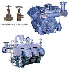
The refrigerating compressor is considered to be the heart of refrigeration and air-conditioning systems. The compressor compresses the refrigerant and consumes most of the power of refrigerating and air-conditioning units.
 The working of reciprocating compressor is very similar to the reciprocating engine used in automotives. The difference is that while the engine generates power, the compressor consumes power and compresses the refrigerant. The reciprocating compressor is comprised of the piston and the cylinder arrangement connected by the connecting rod to the motor shaft. When the shaft of the motor rotates, the piston performs the reciprocating motion inside the cylinder, absorbing and compressing the refrigerant.

 The idealized compressive dynamic turbo-machine achieves a pressure rise by adding kinetic energy/velocity to a continuous flow of fluid through the rotor or impeller. This kinetic energy is then converted to an increase in potential energy/static pressure by slowing the flow through a diffuser. The pressure rise in impeller is in most cases almost equal to the pressure rise in Diffuser section.

All refrigeration and air-conditioning systems have four basic parts: the compressor, condenser, throttling or expansion valve and the evaporator. In refrigeration and air-conditioning units the heat is taken from the low temperature reservoir and thrown to the high temperature reservoir; hence this process requires external power which is given to the compressor.
The compressor sucks low pressure and low temperature refrigerant from the evaporator and compresses it to high pressure and high temperature gaseous state. The larger the size of the refrigeration plant, the larger the compressor will be and the more power will be required.
There are two type of compressors used commonly in the refrigerating and air-conditioning units. These are:
1) Reciprocating compressor
2) Rotary compressors
3) Centrifugal compressor
4) Axial compressor
1) Reciprocating compressor:
Reciprocating compressors can be used for small as well as large refrigerating and air-conditioning units. Their power consumption is more compared to rotary compressors, and they also make more noise.
Reciprocating compressors are of two types:
i) Open type, and ii) Hermetics – totally sealed (welded) and semi-hermetic. The speed of the open compressor can be adjusted as per the capacity requirements. If it is a multi-cylinder compressor, a certain number of cylinders can be bypassed to adjust the capacity and reduce power consumption.
2) Rotary compressors:
In rotary compressors the compression of the refrigerant is achieved by the rotary motion of the rotors instead of the reciprocating motion of the piston. There are two commonly used types of rotary compressors: the rolling piston type and rolling vane type.
· In the rolling piston type a rotor is fixed on the eccentric shaft, which rotates in the cylinder. A vane placed in the slot inside the cylinder acts as the dividing line between suction and discharge of the refrigerant.
· In the vane type of rotary compressor the rotor is concentric with the shaft and rotates inside the cylinder. The cylinder is offline with respect to the motor shaft. Depending upon the capacity of the compressor there may be multiple vanes on the shafts. As the refrigerant enters the compressor in gaseous state it gets trapped between successive vanes and gets compressed. The back flow of gas is prevented by the oil film between the surface of the cylinder and vane tip.
3) Centrifugal compressor:
Centrifugal compressors, sometimes termed radial compressors, are a sub-class of dynamic axisymmetric work-absorbing turbomachinery.
Theory of operation
Imagine a simple case where flow passes through a straight pipe to enter centrifugal compressor. The simple flow is straight, uniform and has no vorticity. As illustrated below α1=0 deg. As the flow continues to pass into and through the centrifugal impeller, the impeller forces the flow to spin faster and faster. According to a form of Euler's fluid dynamics equation, known as "pump and turbine equation," the energy input to the fluid is proportional to the flow's local spinning velocity multiplied by the local impeller tangential velocity.
In many cases the flow leaving centrifugal impeller is near the speed of sound (340 metres/second). The flow then typically flows through a stationary compressor causing it to decelerate.These Stationary Compressors are actually static guide vanes where energy transformation takes place. As described in Bernoulli's principle, this reduction in velocity causes the pressure to rise leading to a compressed fluid.
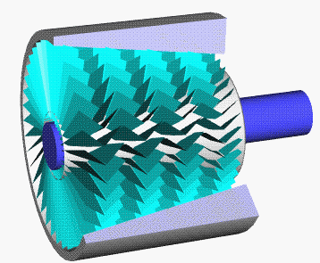
4) Axial compressor :
The compressor is composed of several rows of airfoil cascades. Some of the rows, called rotors, are connected to the central shaft and rotate at high speed. Other rows, called stators, are fixed and do not rotate. The job of the stators is to increase pressure and keep the flow from spiraling around the axis by bringing the flow back parallel to the axis. In the figure on the right, we see a picture of the rotors of an axial compressor. The stators of this compressor are connected to the outer casing, which has been removed and is not shown. At the upper left is a picture of a single rotor stage for a different compressor so that you can see how the individual blades are shaped and aligned. At the bottom of the figure is a computer generated figure of an entire axial compressor with both rotors and stators. The compressor is attached to a shaft which is connected to the power turbine on the right end of the blue shaft. Here is an animated version of the axial compressor:
How does an axial compressor work?
The details are quite complex because the blade geometries and the resulting flows are three dimensional, unsteady, and can have important viscous and compressibility effects. Each blade on a rotor or stator produces a pressure variation much like the airfoil of a spinning propeller. But unlike a propeller blade, the blades of an axial compressor are close to one another, which seriously alters the flow around each blade. Compressor blades continuously pass through the wakes of upstream blades that introduce unsteady flow variations. Compressor designers must rely on wind tunnel testing and sophisticated computational models to determine the performance of an axial compressor. The performance is characterized by the pressure ratio across the compressor CPR, the rotational speed of the shaft necessary to produce the pressure increase, and an efficiency factor that indicates how much additional work is required relative to an ideal compressor.
No comments:
Post a Comment