EXPANSION DEVICES
 The length of the capillary tube of a particular diameter required for an application is first roughly determined by empirical calculations. It is then further correctly established by experiments. The capillary tube is not self-adjusting. If the conditions change, such as an increase in the discharge/condenser pressure due to a rise in the ambient temperature, reduction in evaporator pressure, etc. the refrigerant flow-rate will also change. Therefore a capillary tube, selected for a particular set of conditions and load will operate somewhat less efficiently at other conditions. However if properly selected, the capillary tube can work satisfactorily over a reasonable range of conditions.
 This is similar to the float valves used for water tanks. In a water tank the float valve is fixed at the outlet of the water supply pipe to the tank. When the water level is low in the tank, the float ball hangs down by its own weight and the float arm keeps the valve fully open to allow water flow into the tank. As the water level rises, the float ball (which is hollow) floats on the water and gradually rises according to the water level, throttling the water through the valve. Ultimately when the tank is full, the float valve completely closes the water supply. As the water from the tank is used, the water level falls down; the float ball also lowers down, opening the valve according to the level of water in the tank.
 The name ‘thermostatic-expansion valve’ may give the impression that it is a temperature control device. It is not a temperature control device and it cannot be adjusted and used to vary evaporator temperature. Actually TEV is a throttling device which works automatically, maintaining proper and correct liquid flow as per the dictates of the load on the evaporator. Because of its adaptability to any type of dry expansion application, automatic operation, high efficiency and ability to prevent liquid flood backs, this valve is extensively used.The functions of the thermostatic-expansion valve are:
There are different types of expansion or throttling devices. The most commonly used are:
(a) Capillary tube,
(b) Float valves,
(c) Thermostatic expansion valve.
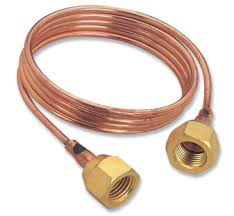
1 Capillary Tube
Instead of an orifice, a length of a small diameter tube can offer the same restrictive effect. A small diameter tubing is called ‘capillary tube’, meaning ‘hair-like’. The inside diameter of the capillary used in refrigeration is generally about 0.5 to 2.28 mm (0.020 to 0.090’). The longer the capillary tube and/or the smaller the inside diameter of the tube, greater is the pressure drop it can create in the refrigerant flow; or in other words, greater will be the pressure difference needed between the high side and low side to establish a given flow rate of the
refrigerant.
The length of the capillary tube of a particular diameter required for an application is first roughly determined by empirical calculations. It is then further correctly established by experiments. The capillary tube is not self-adjusting. If the conditions change, such as an increase in the discharge/condenser pressure due to a rise in the ambient temperature, reduction in evaporator pressure, etc. the refrigerant flow-rate will also change. Therefore a capillary tube, selected for a particular set of conditions and load will operate somewhat less efficiently at other conditions. However if properly selected, the capillary tube can work satisfactorily over a reasonable range of conditions.
As soon as the plant stops, the high and low sides equalise through the capillary tube. For this reason, the refrigerant charge in a capillary tube system is critical and hence no receiver is used. If the refrigerant charge is more than the minimum needed for the system, the discharge pressure will go up while in operation. This can even lead to the overloading of the compressor motor. Further, during the off cycle of the unit, the excess amount will enter the cooling coil and this can cause liquid flood back to the compressor at the time of starting. Therefore, the refrigerant charge of the capillary tube system is critical. For this reason, a refrigerant liquid receiver cannot be used. The charge should be exactly the quantity as indicated by the manufacturer of the refrigeration unit.
Since the capillary tube equalises the high side with the low side during the off cycle, the idle pressures at the discharge and suction of the compressor will be equal. Therefore at the time of starting, the compressor motor need not overcome the stress of the difference of pressure in the suction and the discharge sides. In other words the compressor is said to start unloaded. This is a great advantage as a low starting torque motor is sufficient for driving the compressor.
The capillary tube is quite a simple device and is also not costly. Its pressure equalisation property allows the use of a low starting torque motor. The liquid receiver is also eliminated in a capillary tube system because of the need to limit the refrigerant charge. All these factors help to reduce the cost of manufacture of the systems employing a capillary tube as the throttling device.The capillary tube is used in small hermetic units, such as domestic refrigerators,
freezers and room air conditioners.
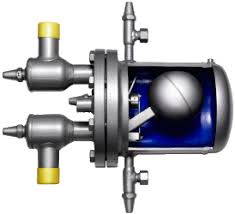
2 Float Valves
There are mainly two types of float valves- low side float valves and high side float valve.
Low-side Float Valve
The low-side float valve also acts in the same way in a refrigeration system. As the name implies the float valve is located in the low pressure side of the system. It is fixed in a chamber (float chamber) which is connected to the evaporator. The valve assembly consists of a hollow ball, a float arm, needle valve and seat. The needle valve-seat combination provides the throttling effect similar to the expansion valve needle and seat. The movement of the float ball is transmitted to the needle valve by the float arm. The float ball being hollow floats on the liquid refrigerant. The needle valve and seat are located at the inlet of the float chamber. As the liquid
refrigerant vaporises in the evaporator, its level falls down in the chamber. This causes the float ball to drop and pull the needle away from the seat, thereby allowing enough liquid refrigerant to flow into the chamber of the evaporator to make up for the amount of vaporisation. When enough liquid enters, the float ball rises and ultimately closes the needle valve when the
desired liquid level is reached. The rate of vaporisation of liquid and consequent drop in the level of the liquid in the evaporator is dependent on the load. Thus the movement of the float ball and amount of opening of the float valve is according to the load on the evaporator. The float valve responds to liquid level changes only and acts to maintain a constant liquid level in the evaporator under any load without regard for the evaporator pressure and temperature.Like in the expansion valve, the capacity of the low-side float valve depends on the pressure difference across the orifice as well as the size of the orifice.
Low-side float valves are used for evaporators of the flooded-type system. In bigger capacity plants a small low-side float valve is used to pilot a liquid feed (and throttling) valve. According to the liquid level in the evaporator, the float valve transmits pressure signals to the main liquid feed valve to increase or decrease the extent of its opening. Thus the low-side float valve in such a system is called a ‘pilot’ and the liquid-feed valve is known as the pilot-operated liquid-feed valve.
High-side Float Valve
The high-side valve like the low-pressure float valve, is a liquid level sensing device and maintains a constant liquid level in the chamber in which it is fixed. However it differs from the low-side float valve in the following respects.
(a) The high-side float valve and its chamber are located at the high pressure side of the system, while the low-side float valve is located at the low-pressure side of the system.
(c) In the high-side float valve, the valve opens on a rise in the liquid level in the chamber, just the opposite action of the low-side float valve, which closes on a rise in liquid level in the chamber.
The high-side float chamber is located between the condenser and
evaporator. The liquid condensed in the condenser flows down to the float
chamber.
As the liquid level rises in the chamber, the float ball also rises, thereby opening the needle valve. As the liquid level falls in the chamber, the float valve tends to close the seat orifice. It is obvious that refrigerant vapour is condensed in the condenser at the same rate at which the liquid vaporises in the evaporator; the float chamber receives and feeds liquid to the evaporator
at the same rate. Since the rate of vaporisation of the liquid in the evaporator is according to the load, the high-side float obviously works as per the load.
This type of float valve is generally used in centrifugal-refrigeration plants.Refrigerant feed/throttling devices for flooded chillers are usually the low side or high-side float valve. For example, in centrifugal plants, the chiller is of the flooded type and generally high-side float valves are used as throttling devices. In a flooded chiller working in conjunction with a reciprocating compressor, a low-side float valve is used as the throttling and refrigerant liquid flow control.
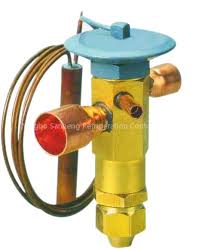
3 Thermo - static Expansion Valve
(a) To reduce the pressure of the liquid from the condenser pressure to
evaporator pressure,
(b) To keep the evaporator fully active and
(c) To modulate the flow of liquid to the evaporator according to the load
requirements of the evaporator so as to prevent flood back of liquid
refrigerant to the compressor.
It does the last two functions by maintaining a constant superheat of the refrigerant at the outlet of the evaporator. It would be more appropriate to call it a ‘constant superheat valve’.The important parts of the valve are:
Power element with a feeler bulb, valve seat and needle, and a superheat adjustment spring.55
Refrigeration
if the capillary was reduced in length or size wouldn't the pressure drop be increased thus giving better cooling
ReplyDelete